The PA3WEG ATV video switching matrix
For ATV, it is sometimes handy to be able to switch a video source on to multiple outputs, and to route video around the ATV shack. This can be done with a video switching matrix, sometimes called a crosspoint switch or video matrix in short. Around October 2013 I had some discussions about such a matrix with a group of ATV enthusiasts. Herman PB0AHX knew of a design to achieve this, but was talking about multiple obsolete ICS.
If there is one thing I hate, it is designing around obsolete stuff! it can not be this hard!
I was right...many ICs exist to achieve the matrix switching function, some of them are easy to obtain for me. So I decided to leave all existing designs behind and design around the Fairchild Semiconductor FMS6501AMTC28X IC. This is a 28TSSOP package SMD component. SMD is not a problem for me. In fact, I prefer it over through hole.
design criteria:
- fast design, we need it now, not in a year
- correct design, no dirty hacks
- No cheap chinese sh*t, but quality components
- relatively compact
- composite video in and out
- software controllable
- Herman PB0AHX is the "launching customer". He decides about features if things are unclear
Design process
I set off finding affordable, simple ICs to do the job. The Fairchild FMS6501 (datasheet)  is "farnellable", You can buy it from farnell, order code 2301764. This IC has all the functionality we want, and the design is a breeze using such an integrated circuit. As always, the data sheets contain a few contradictions.
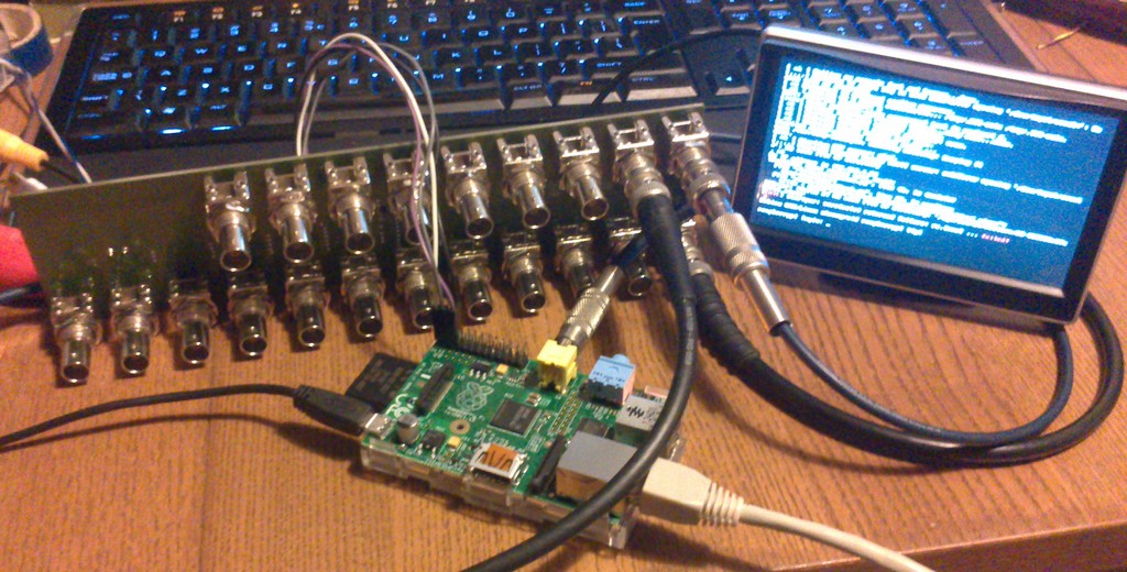
Early on in the project I brought on board Martijn (PB0NER), because I do not have the skills to make a nice I2C library to control the matrix. I will probably have succeeded to control the IC, but in a very messy way, and without user interface. Since I already used the Raspberry Pi as test image generator, it was easy to include that in the matrix. Originally, I had thought to use the Arduino Nano for the task, and this influenced the power supply design. The output of the Pi can also be routed into the video stream. If you attach a video grabber to the Pi, you can also route a video output towards the pi for recording video, creating overlays or taking snapshots.
Early on, a couple of ideas were bounced back and forth between the local ATV enthusiasts, generating many ideas. In the end, I had to limit the implementation of those, to end up with something relatively simple, but fast. Revision B may contain more nice-to-haves.
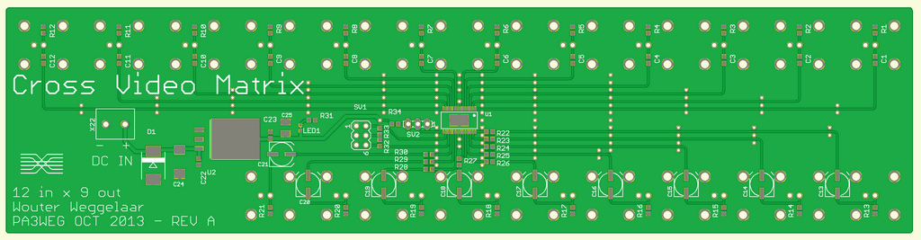
The schematics and PCB layout were done in cadsoft EAGLE, and some early screenshots were circulated for comments. Lots of ideas were discussed in video conferences. The schematics of revision B (pdf) can be found here
It is work in progress, so things may still change as further improvements are made
Design description:
The heart of the system is the aforementioned FMS6501. This IC runs at a minimum voltage of 3.135V, but is typically specified at 5V. It was decided to run the IC at 5V. A small 5V linear power supply is formed around U2, LM1086CS-5.0. This includes the protection diode, buffer capacitors and power LED. This supply was meant to be available on header SV1 but in revision A, I forgot to route that pin. The I2C interface also goes to this header, and has optional pull-ups to VCC. The address of the chip is selected by SV2. The power supply pins can be used to take 5V from the matrix, or to feed power into the matrix if the regulator is not populated. Leaving the regulator in place will not damage it as long as the input is not shorted. NOTE: The power supply is not designed to deliver substantial amounts of power. Although the chip can deliver 1.5A no problem, the heat sink area is not sufficient to dissipate the heat.
WARNING: the I2C lines are 5V, and the Raspberry Pi expects 3V3. The chip may be used at 3v3, but I did not check its performance yet!It should be possible to populate the regulator with its 3v3 variant, and use the raspberry without a level shift, but I am now using a logic level shifter on the raspberry pi
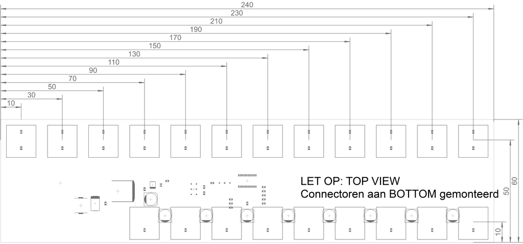
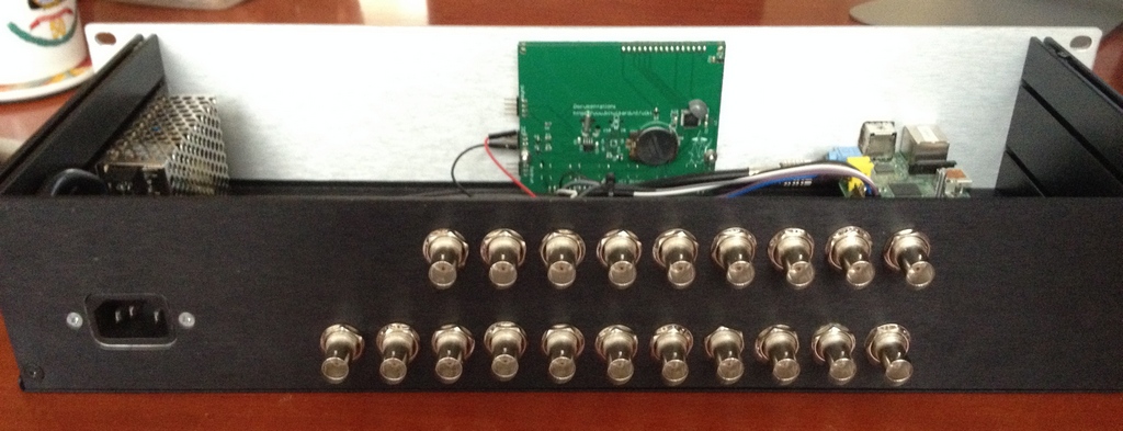
Each video input and output consists of 75 Ohm BNC straight PCB mounted connectors, Amphenol type B6251G3-NPP3G-75T, to allow the board to be fitted in a case attached to the BNCs. These BNCs can also be reversed to the other side of the PCB, to allow internal connections for, for instance, the Raspberry Pi video input. Each in- or output is AC coupled, and terminated in 75 Ohm. On the outputs, the 75 ohm resistor is optional. Mount it in case the load is high impedance. This is not recommended unless no other option is present, for instance if a high-impedance device has an attached cable. I have seen some cheap chinese video monitors that have 10kOhm input impedance and no real coax inputs.
Software
The Raspberry Pi is used to control the matrix using software made by Martijn PB0NER. The first test code he sent me worked straight away.
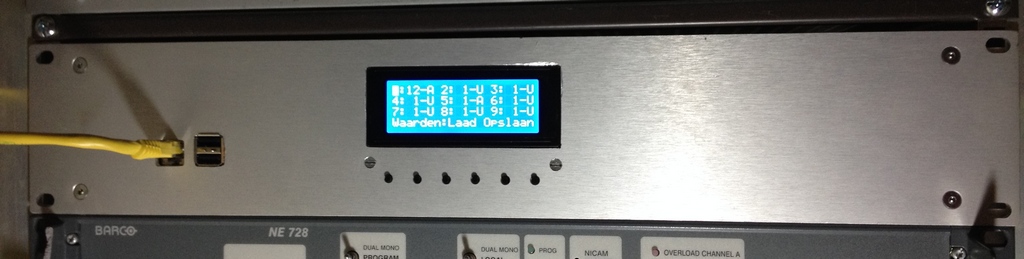
The Raspberry Pi is controlled through the user interface, made by BitWizard. This interface provides a 4x20 LCD and 6 buttons, to control the matrix. The code is written in python. a library is available from martijn for the FMS6501. The library (atv.py) is part of a bigger project with several libraries in it, called "bw_library". These are support libraries for BitWizard products such as the used interface.
The example code is also work in progress, but at the moment the software enables you to:
- control the input to output routing
- control the gain settings
- Work in progress: control the video clamping
- Generate test card images on the raspberry Pi output
The build
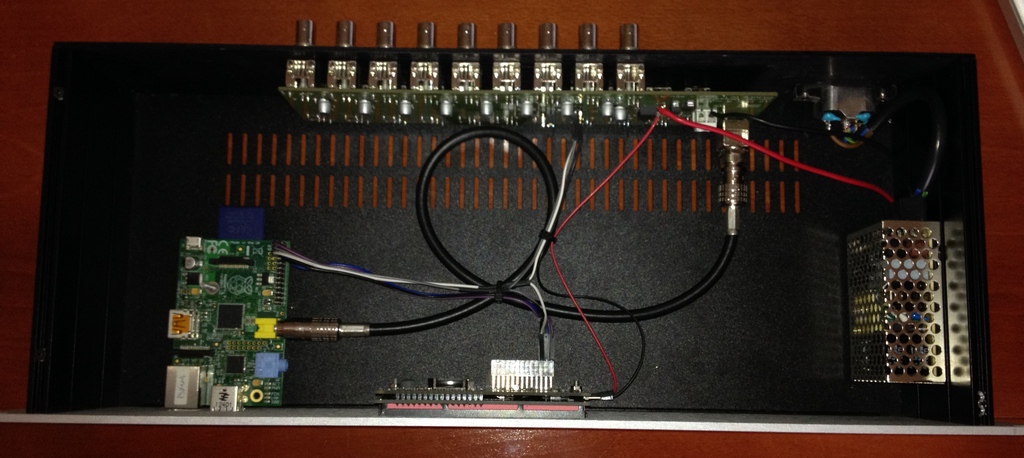
After the PCB was done, some things needed to happen. Mainly putting the matrix in its case, add the power supply and control stuff, and software testing. I assembled the PCB, with all small parts first. After this the bigger parts like the coupling electrolytes. Finally, the BNCs were added. When I hooked up my Raspberry Pi and loaded one of Martijns first trial scripts, I could now route video! so it was first time right on both hard- and software. After this experiment, the board was given to Martijn for further testing and integration. In the mean time, Terry (PD3T) had started milling the front and back panels of the case. This case was already bought by Herman for the purpose. Terry milled the front and back panels to fit he matrix PCB and power entry in the back, and the Raspberry Pi and User Interface in the front. The final product can be seen below. Note the Real time clock backup battery visible on the user interface. This clock can provide an keep the correct time in the raspberry pi when no network time is available.
The version that was delivered to Herman PB0AHX has now functioned for over a year with only one major glitch: some of the wiring came loose from the headers when the matrix was transported to another location. We have now secured these wires and it works flawless.
Pictures
 |
 |
 |
Last modification on: 23 Feb 2016. File: pa3weg/matrix.php