The loop experiments
Early in Februari 2009, Wouter Jan (PE4WJ) and myself were discussing experiments to conduct. We hatched the plan to build loop antennas for experiments during the VERON Pinkster Kamp (VPK)
More info about Wouter Jans loop experiments can be found on his site.
Requirements
- Portable
- Robust
- Usable on at least 80m
- Use of normal hardware, no hard parts
- easy to construct
To further complicate thing, both Wouter Jan and I do not have a large space to place huge loops. We both dont have a garden. We went to the hardware store to buy us some first class engineering material: Copper water piping.
Standing in the hardware store we should have known before: Copper is expensive! I settled on building a 1 by 1 meter square loop and Wouter Jan on a 2 by 2 one so we could compare the results. We bought the stores complete stock of copper and went home with all the copper securely taped to our bikes, hi!
 | 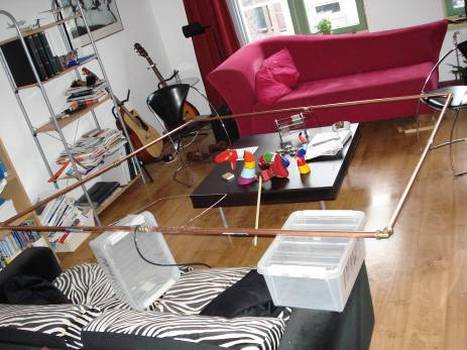 |
| 1m x 1m loop PA3WEG | 2m x 2m loop PE4WJ |
The first plan was to build an octagonal loop using 45 degrees angled pipe fittings, but those were not available. We use clamp fittings. Before everyone starts emailing about loop resistance and the importance of good conducting contacts and the benefits of soldering, welding or even round loops from single pieces of tube, The loop should be Portable.
Step one: Shape
Already determined by the available options. Square it is. Using clamp fitting joints.
Step two: Pipe size.
The largest one available at the normal cheap hardware stores here in holland is 22mm diameter. Thats exactly the one we chose. More diameter means more outer surface, and more outer surface means less RF resistance. The inside of the pipe is not important as all current goes through because of the skin effect. Wall thickness is not something you can choose at the store, so 22mm is fine by us.
Step 3: Tuning capacitor.
The loop antenna is tuned for resonance with the aid of a tuning capacitor. Calculations of the neccesary capacitor vary wildly with the used software and/or formulas in various literature. The spreadsheet loop calculator available on the website of OH2KFH here yields 551pF on 3.7MHz. This calculator is designed for round loops!. However, we can use this value as estimate and experiment a bit with capacitors. All the calculations depend on assumptions about the typical construction of a loop, so even with very precise calculations, experiments are neccesary anyway. (unless you are a antenna wizzard off course hi :-).
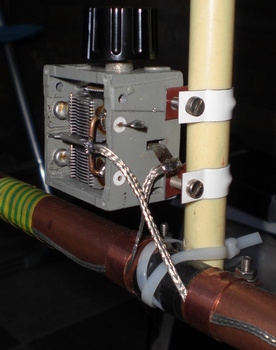
The only reasonable tuning cap around was a two-section radio receiver cap. With the two sections in parallel it can just tune the 80m band with the plates nearly in. Although I did not measure the capacitance, I suspect its something of about 500 - 600pF max. If you want to be able to transmit with more than QRP (> 5Watts) you'll need a capacitor with a high working voltage. Vacuum capacitors are the best for this but are also expensive. Typically you'll need at least 1mm of gap between the plates for each kilovolt. When the air is humid, you'll need more. If you run high power with a small plate separation, arcing may occur. This happened to Wouter Jan and I made a movie of this.
If you do not have a sufficient high valued capacitor you might want to add a fixed value capacitor in parallel to your variable one. This can be a good quality vacuum one, a cap made of PCB material, or a piece of coax used as capacitor. This coaxial capacitor is made of a low loss coax cable like aircell 7. Please note that the coax length should be much smaller that the wavelength. Otherwise, the transmission line properies of the coax become important and you cannot see it as a capacitor anymore!
 |  |
| PE4WJ tuning C | PA3WEG tuning C |
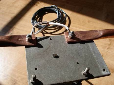
Step 4: Low resistance mounting.
This step is very important for the efficiency and Q-factor of the loop. Mounting the capacitor to the loop using a low RF-resistance path lowers the losses in the tuned RC loop circuit. Lower losses mean higher Q, and higher Q also means more selectivity. And selectivity is something you WILL need in crowded radio traffic. If you make the loop too selective, for instance a bandwith of abt. 1kHz, you are starting to distort SSB signals themselves. Tuning the loop then also becomes more critical. Generally speaking, it will not harm to design for maximum Q-factor because 1kHz bandwith is not likely to occur, and if it does, you know what to do about it.
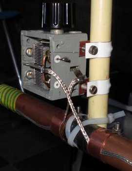
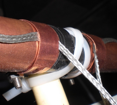
Wouter Jan has a capacitor with the loop directly attached to it, so the RF resistance is low here. Soldering the loop directly to the plates would be even better, but thats simply not achievable with this capacitor. My cap is a differen story. Its not designed for transmitting so the contruction is a bit fragile. I made the connections to the loop using copper braid from a RG-58 coaxial cable. The many small wires reduce the RF-resistance caused by the "skin effect". The two ends of braid are clamped onto the copper using two copper mounting saddles normally used to attach the pipes to the wall. Testing has shown that even this mounting system produces considerably more loss than the method of direct attachment, and is only to be used if there are no other options. The next test is going to be direct mounting for me as well.
Step 5: Coupling loop
The coupling loop of this loop antenna is VERY IMPORTANT. Its location, shape and size make HUGE differences in the loops performance. Using a circular loop seems to be better than a square one. The distance between the couling loop and the main loop is at its closest point about 2cm. Essential in this whole story is that you should adjust the pickup loop for best SWR results and play with loop tuning at the same time. More experiments will have to be performed to see the behaviour.
To be continued......... [last update 24 january 2010]
Last modification on: 23 Feb 2016. File: pa3weg/loops.php