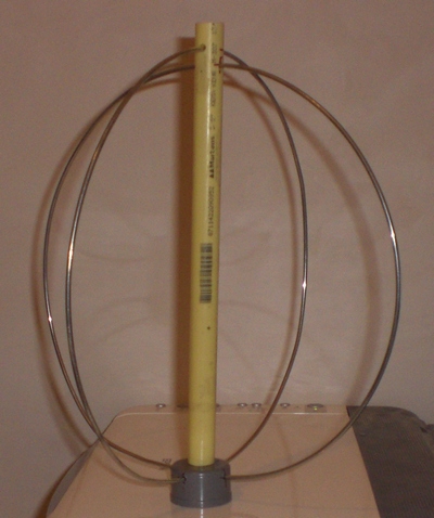
The eggbeater antenna
Because I wanted to be able to work some sats I liked to have an antenna for 70cm circular polarized. At the delfi groundstation we use an omnidirectional "eggbeater" antenna (guess why it has that name..!). This gives such a performance that plans were made to construct one. Wouter-Jan PE4WJ and myself began building some experimental eggbeater projects and below is what I have right now. Some consideratioms for my version included:
- Cheap
- Good to reproduce
- Easy
- Readily available parts
- Reasonable performance, I dont mind losing a few dBs of gain if that produces an easy antenna
First of all, I decided the loops should be made of 6mm2 solid copper wiring with nickel plating. This is because I have about 20 meters of that stuff lying around and its nice and sturdy, still easy to bent by hand. PE4WJ used some surplus semi-rigid he had lying around
Second, the descision was made to use terminal blocks soldered to copper clad board to attach the loops.
Recipe:
- Decide where the PCB is going to fit in and cut it to size.
- Take some terminal blocks and screw out the captive screws. Then gently push the contact out of the plastic. DO NOT LOSE THE SCREWS!
- create isolated islands of copper using a hacksaw, dremel tool or whatever you have handy
- solder the terminal blocks to the board
- cut 2 pieces of 76cm wire to form the loops and bend them to loops
- create a spacer to seperate the two loops at the top. use your imagination!
- hook up the loops and attach a coaxial cable


For now, I wired the loops in parallel so they are NOT phased. This does not create a cicular field, but is can be used to test for resonance (and work in the local net HI)
By now, the antenna is wired with loops in parallel for several weeks, and I think I'm gonna stick with this for this first prototype. As a local net antenna it is good enough. The first crude SWR measurements suggest that there is not much reflected power. The directional couplers in the RS9044 transceiver are fed to ADC inputs and the voltages are readable in the software. IF the forward and reflected voltages are correctly measured the VSWR is about 1 : 1.18, which is a number with a much to large precision for the simple measurements taken. However, it does suggest good performance with VSWR at least lower than 1 : 1,5.
Terminal blocks seem to be a good idea for quick attachments of the loop, but the things have a round bottom and thus won't keep lying flat on the PCB while soldering. This is not very convenient! I will try to come up with another method of attachment.
I'm gonna have a second attempt at a circular one within a short period, And maybe dig up some theory. More to follow! stay tuned..
Last modification on: 23 Feb 2016. File: pa3weg/eggbeater.php